
How Clamp Current Transformers Work
How Clamp Current Transformers Work
1.Introduction
Clamp Current Transformers (Clamp CTs) are widely used in electrical power monitoring systems to measure AC current without directly touching or cutting the conductor. They are essential in industrial automation, solar power monitoring, energy management systems, and smart grids.Unlike traditional current transformers, clamp-type CTs can be installed quickly by simply “clamping” around an energized wire, making them safe, convenient, and cost-effective.
But how exactly do clamp current transformers work? Let’s break it down step by step.
Pls check our products for reference:
https://www.jshelectronic.com/
2.What is a Clamp Current Transformer?
A Clamp Current Transformer (Clamp CT) is a type of transformer designed to measure alternating current (AC) flowing through a conductor using electromagnetic induction.
It consists of:
*A split magnetic core (allowing it to open and close like a clamp)
*A secondary winding coil
*A housing with a spring-loaded or locking mechanism
Because it does not require wire disconnection, it is also called a non-invasive current sensor or split-core current transformer.
3.How Clamp Current Transformers Work (Core Principle)
The working principle of a clamp current transformer is based on electromagnetic induction.
Step-by-step working process:
1.Primary conductor acts as a single-turn primary winding
The electrical wire carrying AC current passes through the center of the CT. This wire itself acts as the primary winding.
2.AC current creates a magnetic field
When alternating current flows through the conductor, it generates a changing magnetic field around it.
3.Magnetic core captures the flux
The clamp CT’s iron core concentrates and guides this magnetic flux efficiently.
4.Secondary coil induces current
The changing magnetic field induces a proportional current in the secondary winding.
5.Output signal is measured
This secondary current is converted into a measurable signal (commonly 1A, 5A, or mA output) and sent to meters, PLCs, or monitoring systems.
Key idea:
The clamp CT does NOT measure current directly. It measures the magnetic field created by the current and converts it into a proportional output signal.
4.Simple Electrical Principle
Clamp CTs follow the basic transformer relationship:
*Primary current → magnetic flux → secondary current
The ratio between primary and secondary current is determined by the turns ratio of the transformer.
Example:
*100A primary current → 5A secondary output
*Ratio = 100:5
This allows safe measurement of high currents using low-level signals.
5.Types of Clamp Current Transformers
1. Split Core CT
*Core opens like a clamp
*Easy retrofit installation
*Most common type
2. Solid Core CT (less common in clamp form)
*Requires wire to be threaded
*Higher accuracy in some cases
3. Flexible Rogowski Coil (alternative technology)
*Measures AC current using air-core coil
*Suitable for large conductors
6.Applications of Clamp Current Transformers
Clamp CTs are used in many industries:
⚡ Power Monitoring Systems
*Energy meters
*Smart grid monitoring
*Sub-metering systems
☀️ Solar PV Systems
*String current monitoring
*Inverter performance tracking
*Fault detection in solar arrays
Please Feel free to give your inquiry in the form below.We will reply you in 24 hours.
CATALOG
-
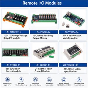
Remote IO Modules Catalog
Industrial IO Modules provide reliable signal acquisition and control so
-
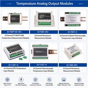
Temperature Analog Output Modules Catalog
High-performance temperature analog output modules for RTD and thermocou
-
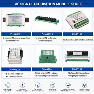
AC Signal Acquisition Modules Voltage Current Monitoring
AC signal acquisition modules for voltage, current, power, energy, and f
ARTICLES
- AC/DC Universal Data Acquisition Module: A Reliable Solution for Data Center Load Aging Testing
- DC Current Monitoring for Solar Combiner Boxes | PV String Current Monitoring Solution
- Current Monitoring Solutions for PV Power Plants
- How to Choose a Data Acquisition Module
- RS485 Modbus Data Acquisition Guide
Contact Us
| Contact: | Maggie Xian |
|---|---|
| Phone: | 8613450868908 |
| Email: | maggie@jshelectronic.com |
| Address: | Plant No. 2, Lijincheng Science and Technology Park, Jihua Road, Longhua Street, Longhua District, Shenzhen City, Guangdong Province |